Your Lumina LSC-400 or LSC-400B controller contains an Accessory Connector that provides six I/O lines. This page shows how to connect these lines to a PC’s parallel port.
Physically, the Accessory Connector uses an RJ45 jack, the same used by standard Ethernet networks. A parallel port uses a DB25 connector (also called DSub25). You need the following parts:
1.
A standard network cable.
2.
Most laptops and many desktop computers no longer come with a built-in parallel port. If you need to buy a USB to parallel port converter, make sure that the supplied drivers will install a virtual parallel port. For example, Keyspan’s Mini Port Replicator installs a virtual parallel port on Mac OS but only a “USB Printing Services” port on Windows, so it will not be useable with a Windows software package that is looking for something like an LPT1 or LPT2 port.
As you can see from the picture, the L-com adapter comes with 8 wires that can be plugged into any of the 25 pins. The Accessory Connector’s six data lines need to go into the DB25 connector’s pins 2, 3, 4, 5, 6, and 7. For example:
DB25 Pin Number
Wire Color
Corresponds to Accessory Connector’s Line
1
Blue
AC1
2
Orange
AC2
3
Black
AC3
4
Red
AC4
5
Green
AC5
6
Yellow
AC6
7
White
Ground
Do not connect
Brown
See below
The brown wire is 5 volts and should not be connected to anything. It would be a good idea to cut the pin off to prevent accidents. The parallel port uses pins 18 to 25 for Ground. They are usually connected together in the PC but it’s not guaranteed.
Finally, you need to make sure that Accessory Connector is setup up correctly to match what the parallel port is expecting. This can be done using the Xidon (pronounced Zydon) utility program. It is a Windows program and can be downloaded from here. Once downloaded and installed:
1.
Make sure that your Lumina controller is turned on and connected to the PC’s serial port.
2.
Set the Mode to “Lumina”. Any speed/baud rate will work.
3.
Run Xidon
4.
Click on the Device menu and select Accessory Connector. A dialog appear:
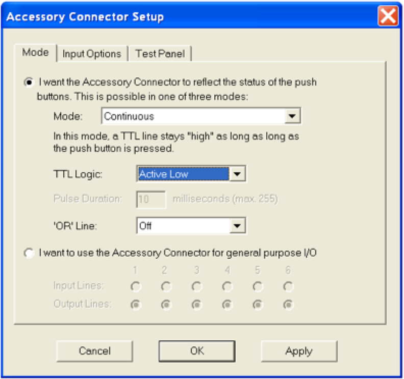
5.
In the Mode tab, set the TTL Logic is set to “Active Low”.
6.
In the Input Options tab, set the input lines to “Pulled High”.
7.
Click on the Apply button.
8.
Click on the OK button to close the dialog.
Once configured in Xidon, the Lumina controller will remember the settings in flash memory.
Last revision: December 11, 2008
PRODUCTS
SUPPORT
STAY IN TOUCH
© Copyright 2026 Cedrus Corporation, P.O. Box 6309, San Pedro, CA 90734 - USA
Phone: +1-310-548-9595. Send us an email
qwerasdf