The RB-x30 response pads include an Accessory Connector that offers up to six I/O (input/output) lines. These I/O lines can be used to connect external peripherals such as additional keys or a foot pedal, or to obtain a TTL output of the built-in keys. This document describes the software and electrical features of the Accessory Connector.
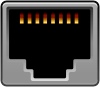
The Accessory Connector uses an RJ45 jack. This is the same type of jacks used in Ethernet wiring, making it easier for find and buy matching cables in a wide variety of lengths and colors.
The RB-x30 response pads do not have their own power supply. They draw power from the computer’s USB port. Because of this, you can draw a maximum of 10 milliamps per pin from the Accessory Connector, and a combined maximum of 50 milliamps total.
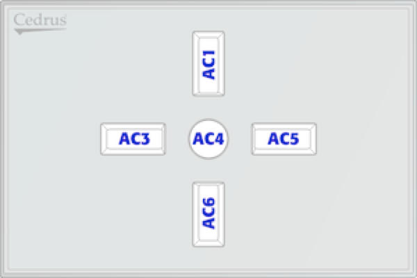
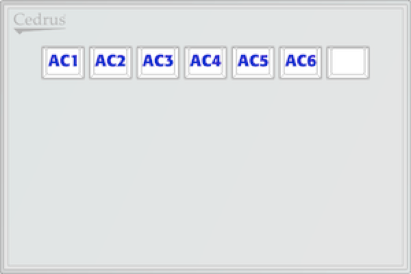
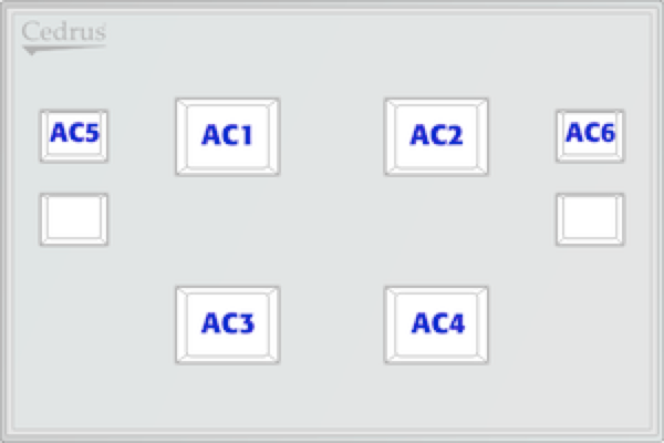
The RJ45 jack has eight pins. One is ground. Another is positive voltage. The remaining six are I/O lines. The table below describes the pin assignments. Pin 1 is the leftmost pin when you are looking at the connector.
Pin
Line
1
Line AC1 (leftmost pin)
2
Line AC2
3
Line AC3
4
Line AC4
5
Line AC5
6
Line AC6
7
+5 volt ±5%
8
Ground (rightmost pin)
Accessory Connector
When in Reflective mode (the default), a key on the response pad corresponds to the following Accessory Connector pins:
RB-530
RB-730
RB-830
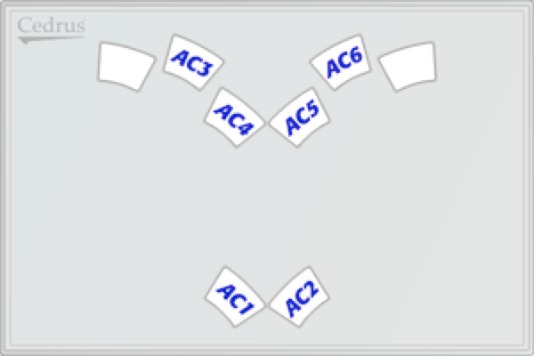
RB-834
The RB-x30 response pads use an “active low” logic. In other words, when the voltage on an I/O pin is around 5 volts, the line is considered OFF. When the voltage is near zero, it is considered ON. Therefore, your own switch should connect between the desired I/O line and ground (pin 8). An active low approach may seem upside down to some, but it is a common practice in electronics.
If you are planning on connecting a switch, it is important that you become aware of debouncing issues.
What is it? When a key is pressed once on the keyboard, we take it for granted that one and only one letter is typed. In reality, closing a switch causes the two metal contacts to touch each other several times over a period of time. This is called bouncing.
Debouncing is a method used to recognize the first switch closure but ignore subsequent bounces. This can be done using either hardware or software. The RB-x30 response pads have a built-in microprocessor, so debouncing is implemented using software. The basic software method is to simply ignore subsequent bounces for a certain amount of time. There is no delay between the key press and the information about it being sent to the computer.
In the RB-x30 models, the timeout duration can be set by the user. It is applied intelligently. For example, if you set the debouncing duration to 5 milliseconds and the user presses a switch at time T, then all subsequent input on this switch is ignored until time T+5 milliseconds, but meanwhile input on all the other switches is still detected even at time T+1.
If you are doing your own programming, see the XID “Set Debounce Time” command.
Last revision: February 18, 2004
PRODUCTS
SUPPORT
STAY IN TOUCH
© Copyright 2026 Cedrus Corporation, P.O. Box 6309, San Pedro, CA 90734 - USA
Phone: +1-310-548-9595. Send us an email
qwerasdf