There are times when you want StimTracker to detect the onset of an external input, e.g. a switch, a foot pedal, or even a TTL signal that’s coming from another computer. There are two ways to do this.
The light sensor inputs can also be used to connect a switch or TTL input on StimTracker Duo and StimTracker Quad. You will need a cable with a 2.5mm connector, available from Amazon and many others:
Here are some important notes:
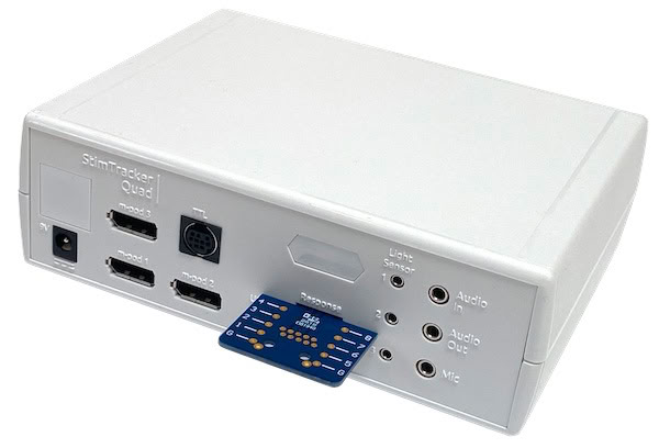
The Quad model includes a built-in connector that allows up to 8 lines of digital input. You can provide digital signals from a computer. You can also connect switches if you use an external power source like a battery. Internally, these lines are wired in parallel with input from a response pad and are pulled down by 10kOhm resistors. It is not possible to use the external input connector and a response pad at the same time.
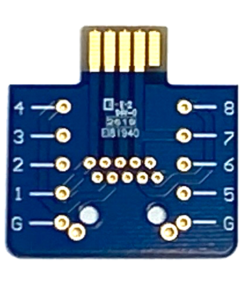
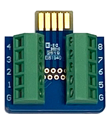
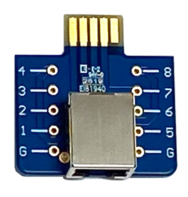
Cedrus has developed a circuit board that would make it easy to take advantage of this connector. It is offered in three variations:
The inputs are active high and have 10kΩ pulldown resistors to prevent floating inputs when not connected.
As far as StimTracker Quad is concerned, input received via an external PCB is identical to input received from a Riponda or an RB-x40 response pad. Corresponding event markers will go out via an m-pod or the Quad’s TTL Output connector.
StimTracker can also produced time-stamped output via USB. This option is turned off by default; see Enabling StimTracker USB Output.
When a mechanical switch is pressed, its contacts will “bounce” a few times, causing several signals to be produced. The size and quality of the switch determines how long it takes for the bouncing to die down. You can “debounce” the switches using a hold-on filter; see XID Filters and Signal Flow.
Last Revision: Dec 19, 2024

PRODUCTS
SUPPORT
STAY IN TOUCH
© Copyright 2026 Cedrus Corporation, P.O. Box 6309, San Pedro, CA 90734 - USA
Phone: +1-310-548-9595. Send us an email
qwerasdf