Cedrus is grateful to Dr. Rohit Tyagi for being generous with his time. He is the author of this support page in its entirety, including screenshots. Dr. Tyagi is with Aerobe, a distributor of Cedrus products in India, Singapore, Malaysia, and other countries.
Even though this page is titled “Using StimTracker with E-Prime 3”, the same instructions can be used for sending event markers via c-pod or via an RB-x40 response pad.
When StimTracker is connected to a PC using the USB cable, it will show up as a COM port in the Device Manager under the section “Ports (COM & LPT)”.
You can close the Device Manager window.
In E-Prime, open the paradigm that you want to modify for sending out triggers using StimTracker:
Next, select the newly added Serial device and click on the Edit… button to set it properties:
Make sure to match the settings as shown above.
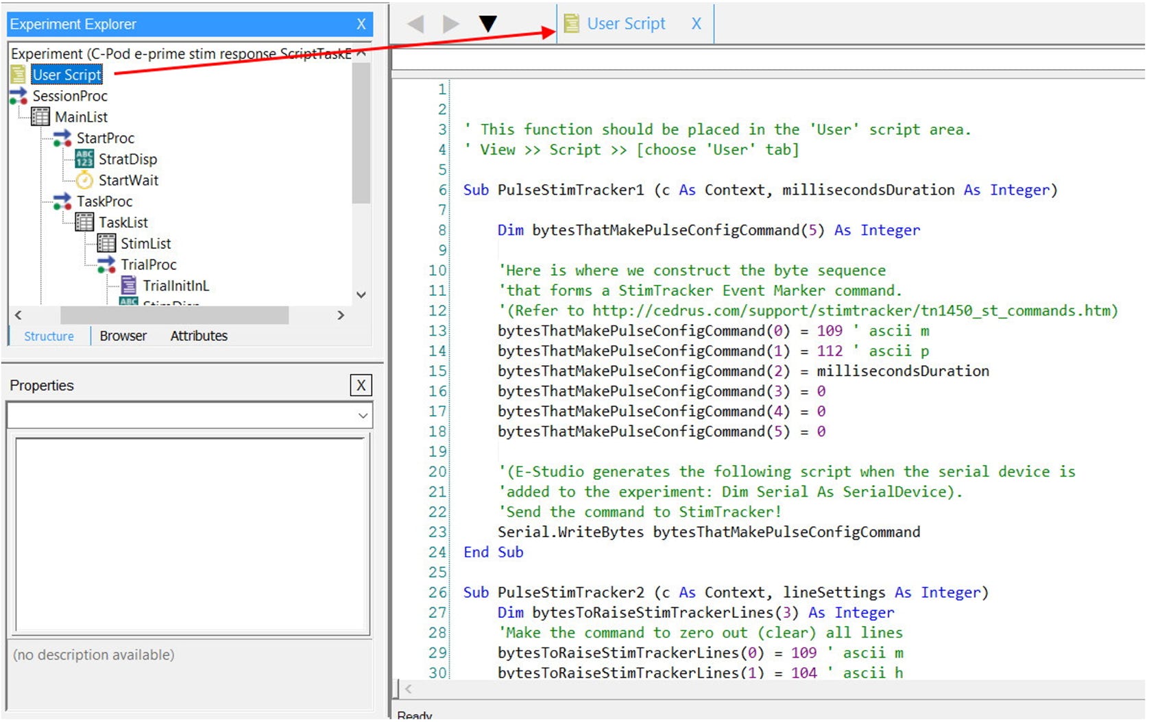
Open the “User Script” section and paste the following lines in it:
' This function should be placed in the 'User' script area.
' View >> Script >> [choose 'User' tab]
Sub PulseStimTracker1 (c As Context, millisecondsDuration As Integer)
Dim bytesThatMakePulseConfigCommand(5) As Integer
'Here is where we construct the byte sequence
'that forms a StimTracker Event Marker command.
'(Refer to http://cedrus.com/support/stimtracker/tn1450_st_commands.htm)
bytesThatMakePulseConfigCommand(0) = 109 ' ascii m
bytesThatMakePulseConfigCommand(1) = 112 ' ascii p
bytesThatMakePulseConfigCommand(2) = millisecondsDuration
bytesThatMakePulseConfigCommand(3) = 0
bytesThatMakePulseConfigCommand(4) = 0
bytesThatMakePulseConfigCommand(5) = 0
'(E-Studio generates the following script when the serial device is
'added to the experiment: Dim Serial As SerialDevice).
'Send the command to StimTracker!
Serial.WriteBytes bytesThatMakePulseConfigCommand
End Sub
Sub PulseStimTracker2 (c As Context, lineSettings As Integer)
Dim bytesToRaiseStimTrackerLines(3) As Integer
'Make the command to zero out (clear) all lines
bytesToRaiseStimTrackerLines(0) = 109 ' ascii m
bytesToRaiseStimTrackerLines(1) = 104 ' ascii h
bytesToRaiseStimTrackerLines(2) = lineSettings
bytesToRaiseStimTrackerLines(3) = 0 ' this final byte is currently ignored by StimTracker
Serial.WriteBytes bytesToRaiseStimTrackerLines
End Sub
This text adds two subroutines or Script sections which could be called as Script Task Events later to send out triggers:
See more information about these commands: StimTracker 1G Software Commands and Using StimTracker with E-Prime 2.
In the Stimulus list, you need to add the variable “StimVal” so that each unique stimulus or condition is associated with a particular marker.
For example, when SimVal is 1, this means that marker 1 will be output from StimTracker and so forth (after conversion to binary number by setting appropriate pins high).
In the main trial where stimuli are being presented, an InLine object needs to be created (TrialInitInL) just before the stimulus display object/slide. The following text should be copied to this object.
This is where you set the pulse timing in the variable “millisecondsDuration”. This is currently set as 30. It can be increased or decreased depending on your trigger receiving device, its sampling rate, and your experiment design:
Dim integerVersionOfAttribute As Integer
Dim millisecondsDuration As Integer
Dim flagValueForDisablingPulse As Integer
millisecondsDuration = 30
'set an upper limit for the unique number to be sent out as marker (depends on receiving device)
flagValueForDisablingPulse = 260
' We use "Context.GetAttrib" to get the
' current value of "StimVal" from the StimList.
' (Refer to E-Basic help regarding "Context.GetAttrib")
Debug.Print "atrrib is: " & c.GetAttrib("StimVal")
integerVersionOfAttribute = CInt(c.GetAttrib("StimVal"))
'Just for fun, we will turn pulse OFF for the last few trials
If integerVersionOfAttribute >= flagValueForDisablingPulse Then
millisecondsDuration = 0
End If
'Support Comments: below subroutine call has been moved to StimDisp.OnsetTime
'We will set millsecondsDuration as an attribute to be referenced in the Custom field
'
'PulseStimTracker integerVersionOfAttribute, millisecondsDuration
'Support Comments: setting the first variable to be passed-in as attributes
c.SetAttrib "millisecondsDuration", millisecondsDuration
'Support Comments: we can reference the StimVal attribute directly and pass it into the Script Task Event as Data Type = Integer
Now we have set both the variables – duration of the pulse and the trigger value to be sent out using the variables.
The variable flagValueForDisablingPulse, may or may not be used. Currently it is set to 260, meaning any StimVal up to 260 will be sent out as a marker. If the receiving device can only receive a 4-bit TTL marker, this means it can receive unique numbers 1-15. In this case one can set this flag variable to 15. Ideally the StimVal being sent should be decided in advance and used correctly in the stimulus list.
Go to the main stimulus event or slide on which the marker has to be sent and open its Properties. Go to the Task Events tab.
Then add the Event for which you want the marker to be sent. Here we have chosen to send a marker at the onset of the stimulus. Similarly markers can be sent at correct/incorrect/omitted responses.
For sending one marker (in response to a stimulus or response) - one pair of such Events will be needed.
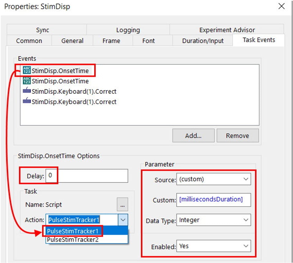
After adding the first StimDisp.OnsetTime event, click on the dots to add a Task and choose “Script”.
Once this is done, in the Action drop down menu “PulseStimTracker1” and “PulseStimTracker2” options will be available.
For the first StimDisp.OnsetTime event, choose “PulseStimTracker1” and configure the other settings as shown above:
This Event will set the pulse width for the marker
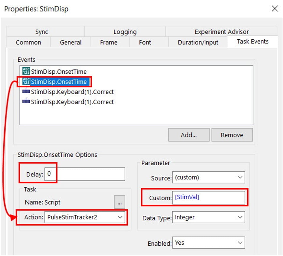
For the second first StimDisp.OnsetTime event, choose “PulseStimTracker2”:
Configure the other settings as shown below.
This Event will set the appropriate pins to high for sending the TTL marker
For sending one marker, both of these tasks events are needed and should be configured as shown. The delay for both these tasks should be set to zero initially.
If StimTracker is not responding as intended, once can change the delay for the 2nd event of the pair (which executes the PulseStimTracker2 code) to “1”, so that this command is only executed after the PulseStimTracker1 command.
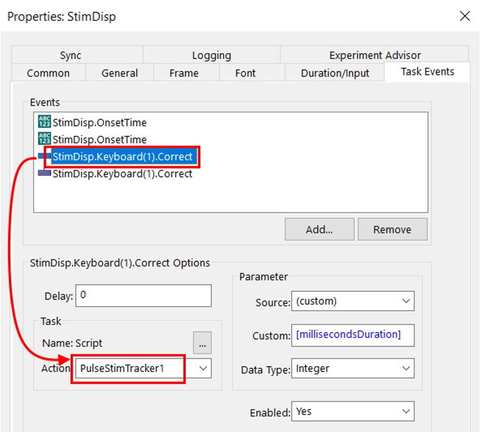
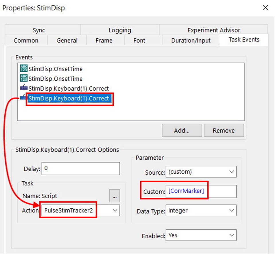
Same way, markers can be sent along for correct or incorrect button presses. The screenshot below shows a pair of Task events to send markers on a correct response.
The one above is to set duration of trigger pulse.
This one above is to set the pins high. Currently this is reading a variable [CorrMarker] from the Stimulus list.
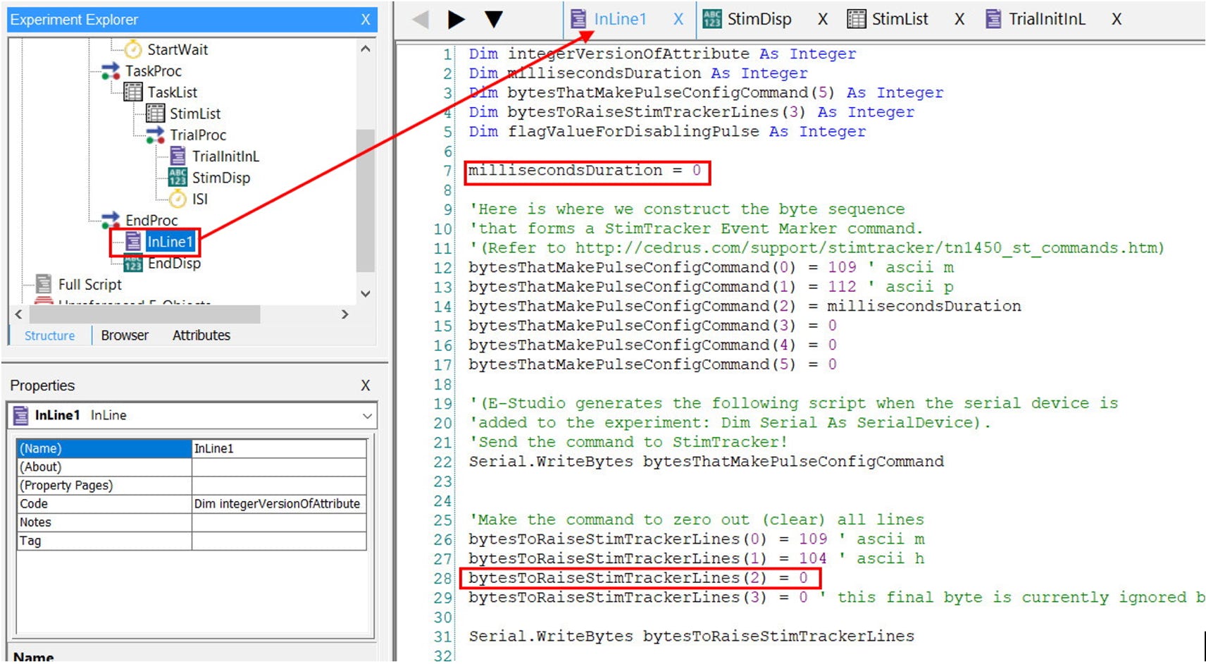
In the end, one InLine object has to be added to set the variables back to zero.
Copy the following code for this InLine object:
Dim integerVersionOfAttribute As Integer
Dim millisecondsDuration As Integer
Dim bytesThatMakePulseConfigCommand(5) As Integer
Dim bytesToRaiseStimTrackerLines(3) As Integer
Dim flagValueForDisablingPulse As Integer
millisecondsDuration = 0
'Here is where we construct the byte sequence
'that forms a StimTracker Event Marker command.
'(Refer to http://cedrus.com/support/stimtracker/tn1450_st_commands.htm)
bytesThatMakePulseConfigCommand(0) = 109 ' ascii m
bytesThatMakePulseConfigCommand(1) = 112 ' ascii p
bytesThatMakePulseConfigCommand(2) = millisecondsDuration
bytesThatMakePulseConfigCommand(3) = 0
bytesThatMakePulseConfigCommand(4) = 0
bytesThatMakePulseConfigCommand(5) = 0
'(E-Studio generates the following script when the serial device is
'added to the experiment: Dim Serial As SerialDevice).
'Send the command to StimTracker!
Serial.WriteBytes bytesThatMakePulseConfigCommand
'Make the command to zero out (clear) all lines
bytesToRaiseStimTrackerLines(0) = 109 ' ascii m
bytesToRaiseStimTrackerLines(1) = 104 ' ascii h
bytesToRaiseStimTrackerLines(2) = 0
bytesToRaiseStimTrackerLines(3) = 0 ' this final byte is currently ignored by StimTracker
Serial.WriteBytes bytesToRaiseStimTrackerLines
Save the experiment and confirm that it is working as intended.
Last Revision: Mar 23, 2022

 in E-Prime.")


PRODUCTS
SUPPORT
STAY IN TOUCH
© Copyright 2024 Cedrus Corporation, P.O. Box 6309, San Pedro, CA 90734 - USA
Phone: +1-310-548-9595. Send us an email. See privacy policy.
qwerasdf