XID
VERSION 2
The commands described here are for the XID 2 class of devices only: Lumina 3G controller, Riponda and RB-x40 response pads, StimTracker 2G, c-pod, and m-pod. Some commands will not work on XID 1 devices, and some XID 1 commands have been deprecated and are not listed here. You can download an archive of the XID 1 commands. Depending on the hardware features, some commands are specific to some devices.
Communication Notes
The intricacy of communications are automatically taken care of by the Cedrus C++ and Python libraries, which you are encouraged to use. But if you choose to communicate with your XID device using raw commands, here are some details to be aware of.
Some earlier XID 1 products required an inter-byte delay. XID 2 devices have faster processors and an improved interrupt structure that eliminates the need for an inter-byte delay.
All XID devices implement a 100ms command timeout. If you send one or more characters that don't eventually become a valid command within 100ms, the device throws those characters out so that it doesn’t get stuck waiting for a character that’s likely never going to arrive.
Command response is (much) less than 1ms. Command response has priority over sending timestamps. So if there were 1000 timestamp reports to be sent and you sent, for example, _d0, the current timestamp would be completed, the response to _d0 would be sent and then the remaining timestamps would follow.
The slowest operations happen when saving to non-volatile flash memory, which takes 50ms. In the case of StimTracker, the CPU is still operating so any serial command or event will be registered during that time. In the case of Lumina 3G, Riponda, and RB-x40, the CPU clock physically stops for 3ms during that period and consequently it could miss a character or event.
Getting Started
Here are bookmarks to the different sections:
m-pod commands are described on a separate page, as are the commands for Analog m-pod and Analog c-pod.
These pages describe additional commands that are specific to:
Saving to flash takes 50 milliseconds on Riponda, RB-x40, and Lumina. It’s noticeably faster on StimTracker, but still, it should not be done while an experiment is running. Some commands will have one of the icons below that affect saving to flash:
Parameter is saved to flash immediately.
Parameter can be saved to flash later using an ‘f9’ command.
On m-pod and c-pod version 2.2.2 or later, the command is locked and the “au” unlock command must first be used.
This documentation applies to firmware version 2.2.1 or later. Each product has its own instructions for updating the firmware: Lumina 3G, Riponda, RB-x40 response pads, StimTracker 2G, c-pod, and m-pod.
Inquiry Commands
These commands provide information about the device, its firmware version, and other properties.
_d0 • Get Combined Info
Returns a text string that is a combination of all the other inquiry commands, plus date and time of the build.
_d1 • Get Product Name
Returns the product’s full name. For example, the Lumina 3G controller returns:
Lumina Standard Controller (3G)
(c) Copyright Cedrus Corporation, 2013
_d3 • Get Specific Model ID
If applicable, returns a single byte to indicate the particular model. For Riponda, RB-x30 and RB-x40 response pads, the following values are returned:
1
2
3
4
Model C / RB-530 / RB-540
Model L / RB-730 / RB-740
Model E / RB-830 / RB-840
Model S / RB-834 / RB-844
For StimTracker 2G:
1
2
3
4
StimTracker Duo
StimTracker Quad
StimTracker Quad with built-in m-pod 4*
StimTrigger
*Included in StimTracker Quad models that started shipping in late 2020.
For m-pod and c-pod:
a
A
B
c
C
D
E
e
F
G
g
H
h
J
M
N
ABM
AD Instruments
Brain Products DB26
Coax / BNC
ANT Neuro
Biopac MP35 / MP36
Biopac MP150 / STP100C
Smart Eye
Biosemi
MindWare (rev A)
MindWare (rev B)
Neuroscan – 16-bit models
Neuroscan – Grael
SMI
Brain Products actiCHamp
NIRx
n
s
S
t
T
P
O
o
i
R
X
Y
U
V
Z
Bittium NeurOne
SR Research
Reserved
TMSi
Tobii Spectrum
Parallel port
EGI (rev A)
EGI (rev B, opto)
iWorx
NeuraLynx
CGX Systems
Natus
Universal/general
Analog
Zeto
For m-pod, see also command ‘_aq’. For all other XID devices, ignore the returned value.
When no model is set, ‘_d3’ returns 0 (ASCII value 48). Note: a ’d3’ command is also available, but is meant primarily for factory use.
_d2 • Get Device ID
Returns a single byte, as follows:
0
1
2
3
4
5
S
C
B
Lumina controller
SV-1 voice key
RB-x30 or RB-x40 response pad
m-pod
c-pod
Riponda
StimTracker
CTB-14 (in-house product)
Buddy Port (unreleased product)
Notes:
- 0 is ASCII value 48, 1 is ASCII value 49, and so forth
- Use command ‘_d7’ to get the generation number
- For m-pod, see the m-pod Commands page
_d4 • Get Major Firmware Revision
Returns a single byte: ‘1’ (ASCII value 49) for XID 1, or ‘2’ for XID 2 devices*. This number is incremented every time there is a significant change to the firmware.
*The first generation StimTracker is not considered an XID device and returns ‘0’ (zero) instead of ‘1’.
_d5 • Get Minor Firmware Revision
Returns a single byte as ASCII value. The minor version is the ASCII value returned minus the ASCII value of ‘0’, which is 48. For example, ‘5’ (ASCII 53) indicates version 2.0.5, ‘Z’ (ASCII 90) is version 2.4.2, and ’b’ (ASCII 98) for version 2.5.
_d6 • Get Outpost Model
For Lumina 3G controller, returns:
0
1
2
3
4
If no outpost is connected
Directly connected OTEC unit
Copper Outpost (supports two OTEC units)
Fiber Outpost (unreleased product)
Embedded OEM Outpost, e.g. built into Invivo’s SensaVue product
Returns ‘x’ for unknown or future outpost models.
_d7 • Get Generation
Returns generation number of the XID product, e.g. ‘3’ for Lumina 3G controller, ‘2’ for StimTracker 2G.
Protocol and Timing Commands
Lumina, Riponda, and RB-x40 response pads support two modes: Standard and Keyboard. In Standard mode, the computer thinks that it has a serial port connected. In Keyboard mode, it thinks that a keyboard is connected.
Protocols for Response Devices
Lumina, Riponda, and RB-x40 response pads can send key press and other event information (e.g. light sensor or scanner trigger) to the host computer in a variety of formats, or protocols. For Standard mode, they are:
- XID: the only protocol that can send time-stamped event information via USB; this eliminates OS timing uncertainties. Timer can be reset via command e5 or via light sensor.
- RB-x20: each bit within the byte indicates which key is pressed. One and only one byte is sent every time a key is pressed or released.
- ASCII: simplest, an ASCII value is sent when a key is pressed. Cannot detect when a key has been released or when two or more keys are pressed simultaneously.
- PST SRB: sends a stream of bytes approximately 800 times per second, each bit within the byte indicates which key is pressed. Implemented for compatibility with E-Prime.
Keyboard mode also supports four different protocols, described in detail elsewhere: see Riponda keyboard mode, RB-x40 keyboard mode or Lumina 3G keyboard mode. Internally, Riponda, RB-x40, and Lumina maintain separate protocol settings depending on the mode; you set the mode protocol for Standard mode using the ‘c1’ command, and for Keyboard mode using ‘c2’.
On Riponda and the RB-x40, you can switch protocols via the DIP switches, but keep in mind that the response pad looks at the position of the switches only when it starts up. If you make changes to the DIP switches, you must restart the response pad for changes to take effect. On Lumina 3G / 3G+, switching protocols is done via two white pushbuttons on the front panel. You can also override the set protocol using a ‘c1’ command.
When using XID protocol and the participant presses a key, the device sends several bytes describing which key was pressed, the port, and the time elapsed. The time elapsed is always relative to the last time the timer was reset. The XID device sends six bytes of information in the following format: <“k”><key info> <RT>:
- The first parameter is simply the letter “k”, lower case
- The second parameter consists of one byte, divided into the following bits:
- Bits 0-3 store the port number:
- For Lumina 3G controller, the value is 0 for the left response pad, 1 for the right response pad and 2 for the light sensor and scanner trigger input.
- For Lumina LSC-400 and LSC-400B controllers, the push buttons and scanner trigger are on port 0; the RJ45 I/O lines are on port 1.
- For Riponda, the value is 0 for key presses, 2 for voice key, and 3 for the light sensor.
- For RB-x40 response pads, the value is 0 for key presses and 3 for the light sensor.
- For the RB-x30 response pads, the push buttons are on port 0 and the RJ45 port is on port 1.
- For SV‐1, voice key is on port 2 and the RJ45 is on port 1 – there is no port 0.
- Bit 4 stores an action flag. If set, the button has been pressed. If cleared, the button has been released.
- Bits 5-7 indicate which push button was pressed.
- The reaction time consists of four bytes and is the time elapsed since the timer was last reset.
Protocol for StimTracker 2G
StimTracker is different in nature. Its USB output is not meant to report participant key presses, but is intended as a time auditing feature or an additional method of obtaining event marker data. This output is turned off by default but can be selectively enabled using the ‘iu’ command. You can also select what StimTracker input source(s) can reset the internal timer using the ‘ir’ command; see Input Commands section below.
Once turned on, StimTracker’s output has the following format:
- The letter “o”, lower case.
- One byte input descriptor, e.g. “A” for light sensor 1 or “K” for response key; see list in the Input Commands section.
- One extra byte that indicates which key was pressed if the input descriptor is “K”; otherwise, it is set to zero.
- One byte indicating if the key was pressed or released; ‘1’ for pressed, ‘0’ for released.
- A 4-byte timestamp.
- A terminating null byte.
Commands
c1 + protocol • Set Protocol for Standard Mode
For all RB models, SV-1, and Lumina only. Sets protocol that should be used for sending key press information and other info when in Standard mode. Send:
c10
c11
c12
c13
for XID protocol
for RB-x20 protocol
for PST SRB / E-Prime protocol
for ASCII protocol
‘c1’ and its equivalent ‘_c1’ are the only two commands that can be used with an XID device regardless of which protocol is currently set. This allows an application to change the protocol to XID in order to send further commands.
Inquiry Command: send bytes ‘_c1’. Returns _xid followed by one byte indicating the current protocol, e.g. ‘_xid0’.
Even though ‘c1’ works only on Riponda, RBs, SV-1, and Lumina, its equivalent ‘_c1’ inquiry command also works on StimTracker and c-pod.
c2 + protocol • Set Protocol for Keyboard Mode
For Riponda, RB-x40 and Lumina 3G only. Sets protocol that should be used for sending key press information and other info when in Keyboard mode. Send:
c20
c21
c22
c23
for XID protocol
for RB-x20 protocol
for ASCII protocol
for PST SRB / E-Prime protocol
c3 • Switch from Standard to Keyboard Mode
Works only with Riponda, RB-x40 and Lumina 3G. Restarting a Riponda or RB-x40 returns it to the mode that’s determined by the DIP switches.
A program can switch from Keyboard mode back to Standard mode by sending there Scroll Lock key presses with no more than 50ms between them.
c4 + mode • Set Polled or Timestamped Mode
Works only with “c-pod for MindWare” or “Universal c-pod”.
Send ‘c4p’ to set polled mode (default). You can retrieve the state of the input lines using the ‘_ic’ command.
Send ‘c4t’ to set timestamped mode. c-pod will send output to the USB port using the XID protocol every time there is a change to the state of the input lines.
Inquiry Command: send bytes ‘_c4’ to get current mode. Returns _c4 followed by t or p.
e5 • Reset Timer
Resets the on-board hardware timer.
Inquiry Command: send bytes ‘_e5’. Returns _e5 followed by four bytes indicating the timer’s value.
Digital Output Commands — Single Pulse
The mp, mh, and ml commands are available on all XID 2 devices as well as the first generation StimTracker. The XID 1 response devices, i.e. the RB-x30 response pads, Lumina LSC-400 controller, and SV-1, used the ap and ah commands instead. For backward compatibility with existing software, the ah command will still work on XID 2 response devices, but it is deprecated and its use is discouraged in new software.
The mx command is available only on XID 2 devices and was introduced in firmware version 2.2.5. Whereas mh will affect all output lines, mx allows output on a specific line without affecting the state of other lines.
Important: mx and mh will have no effect whatsoever on output lines that are masked; see the next section and the mk command.
mp + duration • Set Pulse Duration
Sets pulse duration for subsequent mh commands, in milliseconds. If the duration is 0 [default], then an mh command will set the output lines and hold them; their state will only change when another mh command is sent or an mz command is sent.
The parameter is a four byte binary value that forms a little-endian, 32-bit unsigned integer.
Inquiry Command: send bytes ‘_mp’. Returns _mp followed by the pulse duration.
mh + bit pattern • Generating a Pulse
Sends a pulse whose duration was previously set with an mp command, or raises output lines if that duration is 0. Send bytes ’mh’ followed by two bytes indicating the bit pattern (a binary value) where each bit corresponds to an output line; a ‘1’ will raise the line, a ‘0’ will lower it.
For example, on a c-pod model that supports 16 bits of output, you can set all 16 bits to high by sending four bytes whose ASCII values are 109 104 255 255. 109 and 104 are the ASCII codes for ‘m’ and ‘h’ respectively. 255 and 255 are ASCII values for the bit pattern.
The upper byte of the bit pattern is ignored if the device supports only 8 bits of output.
Inquiry Command: send bytes ‘_mh’. Returns _mh followed by a two-byte bit mask indicating which lines are currently raised — regardless of whether the lines were raised with an mh command or an mr command.
mx + duration + bit pattern + no. of pulses + IPI • Set Output
Can send one or more pulses, raise a line, or lower a line without affecting remaining lines.
‘duration’ is a two-byte parameter:
- A value of 0 lowers the lines that are indicated by ‘bit pattern’
- 0xFFFF raises the lines
- Otherwise send a pulse with the specified duration in milliseconds
‘bit pattern’ is a two-byte value where each bit corresponds to an output line. The output lines indicated by a ‘1’ are affected and the ones indicated by a ‘0’ are left alone.
’no. of pulses’, one byte, is the number of pulses that you want to send. It is ignored if ‘duration’ is set to 0 or 0xFFFF.
‘IPI’ is the inter-pulse interval, two bytes. It is ignored if ‘no. of pulses’ is less than two.
Inquiry Command: send bytes ‘_mx’. Returns _mx followed by one byte: “1” if there is an async pulse sequence running or “0” otherwise. It will also return “0” if all of the bits are at a steady state (either high or low).
ml + number of lines • Set Number of Output Lines
Works only on c-pod and m-pod, tells the device how many output lines it has. The parameter is a single byte binary value. When updating the firmware, the default is 32 bits. This command is intended for factory use.
Inquiry Command: send bytes ‘_ml’. Returns _ml followed by the number of lines.
Digital Output Commands — A Sequence of Pulses
Overview
XID 2 devices have a powerful feature that allows you to send multiple pulses asynchronously. The sequence of pulses can be different on each output line. Or you can have the device send pulses periodically with each output line having a different period — while at the same time retaining the ability to send single pulses out via the mh command. Neat stuff.
One application is to mark important segments in a sound or movie file. Another is the ability to control the intensity of an LED or a tactile stimulator. You can delegate such tasks to an XID 2 device to have it work in parallel with your software.
You do all these things by first populating a pulse table, then sending an mr command to have the device process it. The following example will have the XID device send a 200ms pulse at 0, 1000, and 2000ms. It is presented in pseudocode, but the example also shows the hexadecimal values of bytes you need to send, whether in your code or via RealTerm:
0x6D 0x63
0x6D 0x74 0x00 0x00 0x00 0x00 0x01 0x00
0x6D 0x74 0xC8 0x00 0x00 0x00 0x00 0x00
0x6D 0x74 0xE8 0x03 0x00 0x00 0x01 0x00
0x6D 0x74 0xB0 0x04 0x00 0x00 0x00 0x00
0x6D 0x74 0xD0 0x07 0x00 0x00 0x01 0x00
0x6D 0x74 0x98 0x08 0x00 0x00 0x00 0x00
0x6D 0x74 0x00 0x00 0x00 0x00 0x00 0x00
0x6D 0x72
The resulting output looks like this:

mc
mt 0, 0x01
mt 200, 0x00
mt 1000, 0x01
mt 1200, 0x00
mt 2000, 0x01
mt 2200, 0x00
mt 0, 0x00
mr
// Clear the pulse table
// First param is time offset, second is bit pattern
// Lower lines after 200ms
// Raise line 0 (first line) again at offset 1000ms
// Offset 0 means end of pulse sequence
// Run the sequence of pulses
The next example sends a periodic pulse on two output lines: a 200ms pulse on line 0 and a 500ms pulse on line 1, every second:
0x6D 0x63
0x6D 0x74 0x00 0x00 0x00 0x00 0x03 0x00
0x6D 0x74 0xC8 0x00 0x00 0x00 0x02 0x00
0x6D 0x74 0xF4 0x01 0x00 0x00 0x00 0x00
0x6D 0x74 0xE8 0x03 0x00 0x00 0x00 0x00
0x6D 0x74 0xFF 0xFF 0xFF 0xFF 0x00 0x00
0x6D 0x72
mc
mt 0, 0x03
mt 200, 0x02
mt 500, 0x00
mt 1000, 0x00
mt 0xFFFFFFFF, 0x00
mr
// Clear the pulse table
// Raise lines 0 and 1
// Lower line 0, keep line 1 up
// Lower all lines
// Wait until we have a full second
// Time offset 0xFFFFFFFF means repeat sequence
// Run the sequence of pulses

The XID device will keep sending pulses out until an ms command is sent.
Conflict Resolution
While a pulse table is running following an mr command, you can at any time send a pulse on another line. Let’s say that you have already sent an ‘mp 1400’ command to set the pulse length to 1400ms. One second after running the pulse table, you send ‘mh 0x04’ to send a pulse on line 2. You will get:

But what if, instead, you had sent an ‘mh 0x07’ command, indicating that you want the pulse to go out simultaneously on lines 0, 1, and 2? The result would have been exactly the same thing — only line 2 would have been affected. While a pulse table is running, the output lines that it uses are “locked” and inaccessible to the ‘mh’ command.
XID does this by using a bit mask. You can set the bit mask if you like, but you don’t need to. XID builds the bit mask automatically as you populate the pulse table. Any output line that is specified by the mt command will result in a corresponding bit being set in the bit mask. Then, when you run the pulse table, output will go out only on lines whose corresponding bits are set. Conversely, the mh command will be able to send output only on the lines whose corresponding bits in the bit mask are cleared.
mt + time offset + bit pattern • Add Entry to Pulse Table
The first parameter is a 4-byte binary number that indicates the time offset in milliseconds. There are two special values: 0 indicates the end of the pulse table except when it is the first entry, and 0xFFFF FFFF means repeat the pulse table; more below. The four bytes form a little-endian, 32-bit unsigned integer.
The second parameter consists of two bytes:
- If ‘time offset’ is 0xFFFF FFFF, ‘bit pattern’ indicates the loop count, i.e. how many times the sequence of pulses should be ran. A value of 0 for ‘bit pattern’ indicates an infinite loop.
- For all other values of ‘time offset’, the ’bit pattern’ parameter indicates which output lines should be raised. A value of 0 will lower output lines that were previously raised in the pulse table. It will not affect the state of other output lines that may have been set via an mh command.
You can add up to 200 entries; that’s 100 pulses.
mr • Run the Pulse Table
Starts generating pulses as described by the pulse table. See the Overview above. This command is ignored if the pulse table is already running.
Inquiry Command: send bytes ‘_mr’, returns _mr followed by ‘1’ if the pulse table is running, ‘0’ if it’s not.
ms • Stop Running the Pulse Table
All output lines specified by the bit mask will be set to low.
mc • Clear Pulse Table
Clears all entries in the pulse table and the bit mask. It does not affect the output lines. The bit mask is cleared regardless of whether it was set automatically or via an mk command. The next mt command will start populating the pulse table at the first entry.
Note: this command is ignored if the pulse table is already running.
mk + bit pattern • Set the Bit Mask
Overrides the bit mask that was automatically built by XID with your own. ‘bit pattern’ is two bytes. The set bits will only allow output from the pulse table on the corresponding lines. The cleared bits will only allow output via the mh command on the corresponding lines.
Use this command with caution. The automatic approach that XID uses to build the bit mask covers most use cases.
Inquiry Command: send bytes ‘_mk’. XID returns _mk followed by the bit mask pattern.
mz • Reset All Output Lines
If the pulse table is not running, this command sets all output lines to low, regardless of whether a line was raised by an mh command or pulse sequence.
If the pulse table is running, mz sets all output lines to low except for those indicated by the bit mask.
Input Commands
Different devices support different inputs. XID 2 deals with them uniformly whenever possible. The following table recaps the inputs that are available in each device. m-pod and c-pod do not appear in this table because they are output-only devices:
_
Device
Riponda response pads
RB-x40 response pads
Lumina 3G controller
StimTracker 2G Duo
4
1
Yes
8
8
No
Light Sensor
Mic /
Voice Key
_
Audio
Response
Keys
External
TTL Input
Scanner
Trigger
1
1
No
5 to 8
No
No
1
0
No
5 to 8
No
No
1
0
No
1 to 10
No
Yes
2
0
Yes
8
No
No
StimTracker 2G Quad
Notes:
- On StimTracker Quad, you can use 3 light sensors + voice key, or 4 light sensors but no voice key.
- The “Response Keys” column shows 8 keys for StimTracker 2G. This refers to the fact that StimTracker 2G can be connected to a Riponda or an RB-x40 response pad to mark the onset key presses.
- StimTracker Quad treats response keys and external TTL input as one and the same.
The light sensors, audio, and microphone are analog inputs. The XID device determines an onset when the input crosses a preset threshold. The other inputs are digital and use positive logic by default, i.e. 0 volts indicates a logical 0 and +5V indicates a logical 1. In the following commands, XID 2 uses an “input selector” letter to refer to the different inputs:
A
B
C
D
M
Light sensor 1
Light sensor 2
Light sensor 3
Light sensor 4
Microphone
L
R
K
T
Audio – Left
Audio – Right
Response key (or external TTL input on StimTracker Quad)
Scanner trigger
Each input source can:
- Generate output on m-pod. This can be disabled using the at m-pod command, or better yet, Xidon 2.
- Reset the timer (ir command). By default, only light sensor 1 and audio (either left or right) will reset the timer.
- Generate timestamped output via USB (iu command); this is off by default.
Input Options
ir + input selector + action • Reset Timer on Onset
Indicates whether the specified input should reset the timer. The input selector is one of the letters listed above. ‘action’ is:
0
1
2
Do not reset timer
Always reset the timer on onset
Reset timer on first onset only; XID reverts back to 0 after resetting the timer
With an ‘action’ value of 2, you can control when the XID device resets the timer, e.g. one time only at the start of a trial.
By default, all inputs are set to “Do not reset timer”.
Example: send ‘irD1’ to enable resetting of the timer every time onset of light sensor 4.
Inquiry Command: send bytes ‘_ir’ + input selector, returns _ir followed by input selector and current action.
it + input selector + value • Set Analog Input Threshold
Sets the threshold for the specified analog input. The ‘value’ parameter is a binary number between 0 and 100. This value can be saved to flash memory via an f9 command.
Inquiry Command: send bytes _it + input selector, returns _it followed by input selector and current value.
_ic + port • Get State of Input Lines
Works only with “c-pod for MindWare” or “Universal c-pod”. Returns _ic followed by a single byte that reflects the state of the input lines.
Parameter ‘port’ is always 0.
il + LED action • Enable or Disable Riponda/RB-x40 LED
Allows LED on back of Riponda or RB-x40 to be turned off to avoid distraction. Send ‘il0’ to turn LED off, ‘il1’ to have it indicate detection of light, or ‘il2’ to have it indicate detection of voice via microphone.
Inquiry Command: send bytes _il, returns _il followed by ‘0’, ‘1’, or ‘2.
iv + input mode • Set Mixed Input Mode
For devices that have a mixed light sensor / microphone input jack (currently StimTracker Quad only), this command selects between the two. Send ‘iv1’ to use as voice key / microphone, or ‘iv0’ to use as light sensor.
By default, input is set to microphone.
Inquiry Command: send bytes _iv, returns _iv followed by the current input mode.
ig + output mode • Set Keyboard Auto Repeat
Setting output mode to ‘1’ will allow an operating system to generate auto-repeat keys if a response pad button is held down. The default is ‘0’. Applies to Riponda, RB-x40, or Lumina when used in Keyboard mode.
Inquiry Command: send bytes _ig, returns _ig followed by the current output mode.
Signal Filtering & Flow Control
When a device (StimTracker or response pad) detects an input event, it can report this event via USB and/or via m-pod. XID 2 provides signal filtering and flow control to determine which events are reported and how often they are reported.
The following four diagrams describe the overall signal flow and how you can control it:
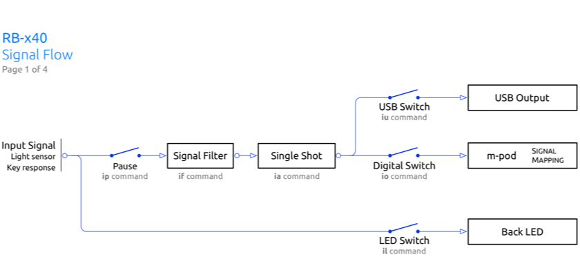
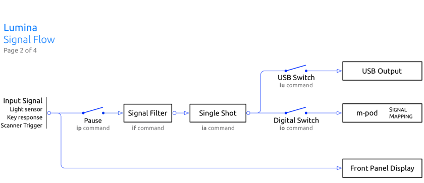
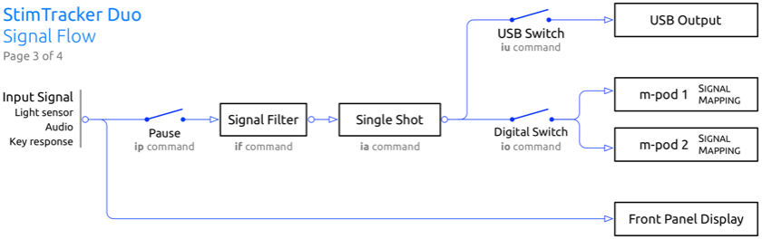
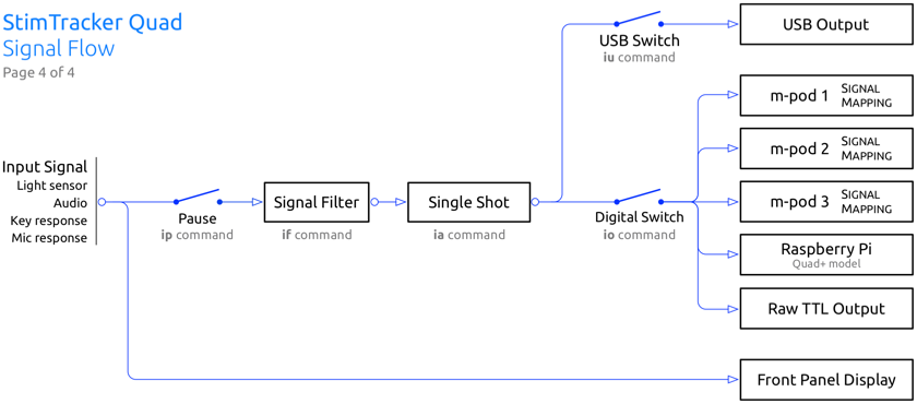
The signal filter (if command) allows an application to limit how many pulses it receives. An example is when playing a spoken sentence or a long audio clip. This could result in too many event markers during lower intonations or pauses; see Signal Flow for more information.
When an event occurs, e.g. onset of a light sensor, single shot allows you to have the XID device produce a single event marker and ignore all the other onsets until you decide otherwise. This can be time-based or under application control. You send an ia command to “arm” the single shot feature.
And last, the iu and io command allow you to enable or disable output to USB or m-pod/TTL. For example, when using microphone for vocal responses, you can turn output on at the onset of a trial and turn it off afterwards. This prevents erroneous event markers from being generated due to speech or sounds unrelated to a trial.
All of the features above can be applied on a signal by signal basis, except for participant key response where noted.
iu + input selector + flag • Enable USB Output
For the designated input, indicates if output needs to be sent via USB. The input selector can be one of the letters listed above, except ‘K’. ‘flag’ is ‘0’ or ‘1’.
By default, timestamped USB output is disabled for all inputs on StimTracker, and is enabled for the light sensor on Lumina, Riponda, and the RB-x40 response pads.
Example: send ‘iuB1’ to generate USB output for every transition of light sensor 2.
Inquiry Command: send bytes ‘_iu’ + input selector, returns _iu followed by input selector and current flag.
ia + input selector + action + delay • Set Single Shot
For the designated input, enables single shot mode. ‘action’ is one of the following values:
0
Single shot disabled, output is unchanged [default]
1
Single shot is enabled with a ‘delay’ reset time.
If ‘delay’ is 0, the single shot will allow only the first output through and block any further output until another ia command is sent.
If ‘delay’ is any other value, single shot is re-enabled after ‘delay’.
‘delay’ is a 4-byte binary value in milliseconds.
Inquiry Command: send bytes ‘_ia’ + input selector, returns _ia followed by input selector, action byte, and four bytes to indicate the delay value.
io + input selector + flag • Enable Digital Output
Indicates whether the specified input should generate output via m-pod, and on StimTracker Quad, via “TTL Output” or Raspberry Pi. The input selector is one of the letters listed above, except ‘K’. ‘flag’ is ‘0’ or ‘1’.
The default is always ‘1’ for all inputs when you power up the XID device, i.e. always send digital output. The m-pod output reflects the input; it remains high until the input source goes off – unless overridden by m-pod’s am command.
Example: send ‘ioA1’ to have light sensor 1 send output for every transition of light sensor 1.
Inquiry Command: send bytes ‘_io’ + input selector, returns _io followed by input selector and current flag.
if + input selector + hold on + hold off • Set Signal Filter
For the designated input, sets the hold on and hold off delay values. Each parameter is a four byte binary value, in milliseconds. See Signal Flow page for the default values.
Inquiry Command: send bytes ‘_if’ + input selector, returns _if followed by input selector and and eight bytes to indicate the two hold delay values.
Miscellaneous Commands
f1 + baud rate • Set Serial Port Speed
Sets the serial port speed of the XID device when it is in Standard mode. Send bytes ‘f1’ followed by one byte indicating the baud rate. Unlike with other commands, the parameter byte for this command is binary, not ASCII:
0x00
0x01
0x02
0x03
0x04
9600 baud
19200 baud
Ignored (was 38400 baud on XID 1)
56K baud
115K baud
After sending this command, you must close the serial port on your computer and re-open it at the new baud rate, otherwise your program and the XID device will not communicate.
The factory default is 115K baud.
f3 • Reprogram Flash
Instructs the XID device to get ready to receive an update to itself.
Do not use this command! If you do by any chance, the XID device will most likely hang. Power it off, wait a few seconds, and then power it back on.
f6 + debounce time • Set Keys Debounce Time
Applies only to Lumina 3G, Riponda, and RB-x40. Sets the push buttons' debounce time. Send ‘f6’ followed by a single byte indicating the debouncing period in milliseconds.
The default is 10 milliseconds. Also, see note below.
Inquiry Command: send bytes ‘_f6’. The Lumina controller returns _f6 followed by the debounce time.
f7 • Restore Factory Defaults
Resets the XID device to its original factory default values. Be careful when using this command because it erases ALL the user settings.
f8 • Flushes the Contents of the Time-stamped Buffer
Flushes / clears the contents of the time-stamped output buffer.
f2 + locking level • Set Locking Level
Deprecated in XID 2.
f4 + trigger default • Set Scanner Trigger Default
Applies only to Lumina 3G and LSC-400 controllers. It sets the default value of the scanner's trigger LED, meaning whether the LED should be normally ON or normally OFF. This value can be saved to flash memory via an f9 command.
The reason for having this command is because the trigger on GE scanners is a differential signal. Because of the nature of this signal, there is no way to determine which value is “on” or “off”.
Send bytes ‘f40’ to set the scanner trigger to “normally OFF” or ‘f41’ to set it to “normally ON”.
Inquiry Command: send bytes ‘_f4’. The Lumina controller returns _f40 or _f41.
f5 + debounce time • Set Trigger Debounce Time
Applies only to Lumina 3G controller (and the LSC-400 controller before it). Send ‘f5’ followed by a single byte indicating the debouncing period in milliseconds.
The default is 5 milliseconds. Also, see note below.
Inquiry Command: send bytes ‘_f5’. The Lumina controller returns _f5 followed by the debounce time.
f9 • Save Parameters
Saves the following to permanent flash memory:
Baud rate (‘f1’ command)
Serial protocol (‘c1’)
Keyboard protocol (‘c2’)
Trigger default (on Lumina) (‘f4’)
Set trigger debounce time (‘f5’)
Response pad debounce time (‘f6’)
Set analog input threshold (‘it’)
Generate USB output (‘iu’)
Generate digital output (‘io’)
Set single shot (‘ia’)
Set signal filter (‘if’)
Set voltage range (‘fv’)
Specific Riponda, RB-x40, c-pod, m-pod, or StimTracker model (‘d3’)
_fo • Returns Status of Optical Isolation Switch
For the Lumina 3G controller’s scanner trigger input, returns ‘1’ if optical isolation is enabled, or ‘0’ if it’s not.
Optical isolation requires a physical switch; the firmware can only report the switch setting.
Note: XID firmware version 2.2 introduces new powerful signal flow filters that supersede commands ‘f5’ and ‘f6’. These two commands remain for backward compatibility, but are now simple wrappers to the ‘if’ “Set Signal Filter” command, where 'f5' is the equivalent of an 'ifTxxxx0000’ command and 'f6' is the equivalent of an 'ifKxxxx0000’ command, ‘xxxx’ being the debounce time.
Last revision: Apr 28, 2026